|
|
||
|
|
||
|
|
||
|
|
||
|
|
||
 |
||
 |
 |
|
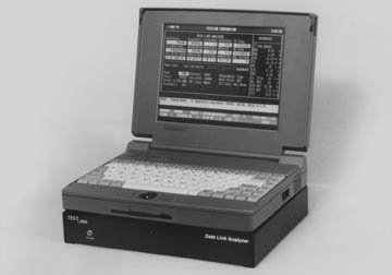
The Telinc Data Link Analyzer II transforms your laptop or PC into a bit error rate tester. You can measure the performance of DDS and similar services, T-1, fractional T-1 and conventional analog facilities, modems, multiplexers, CSU/DSUs and T-1 ESF CSUs. And, you can continue to use your computer for other applications when you are not testing. The compact Telinc unit is connected to the PC's parallel port. It is supplied complete with operating software and a selection of cables. RS422/RS530/X.21, RS232, V.35, DDS (4-wire) and two DS1 (T-1, 1.544 Mbps) interfaces are included as standard equipment. Two Built-in T-1 CSUs With two built-in T-1 CSUs, the Data Link Analzer can be used in a Drop-and-Insert mode to test T-1 facilities and equipment without interfering with the flow of user data. In addition, the Analyzer can be used in DSX Monitor, Terminate and Bridge modes. Test data can be inserted in all or selected DS0s, contiguous or non-contiguous, making it ideal for fractional T-1 testing. The Analyzer counts and/or measures many performance parameters and displays them in the appropriate units (milliseconds, seconds, bits, etc.). |
Built-in DDS CSU/DSU The Analyzer also includes a built-in 56/64 Kbps DDS CSU/DSU with a four-wire interface. It can operate at speeds from 2400 to 72,000 bps. With the CSU/DSU, the Analyzer can test a network or it can simulate a network to test customer DDS CSU/DSUs. Asynchronous and Synchronous Testing In addition to T-1 and DDS, the Analyzer provides asynchronous and synchronous test modes. It generates test data in a choice of patterns and formats. The selected patterns can be transmitted once, at user-selected intervals or continuously. The user can also set up sequences in which the tester steps through a selection of pre-programmed test templates. Help Screens Context-sensitive help screens make the Analyzer easy to use without training and without reference to a manual. All operations can be performed with only a few keys which are defined at the bottom of every screen. Test parameters are selected by scrolling through values stored in the Analyzer software. Each parameter is explained as it is selected. Examples are illustrated for various configurations. The entire manual, service and warranty information and Telinc's toll-free number are available on line. |
| Asynchronous | Synchronous | DDS | T1 | ||
Speeds 50 bps to 115 Kbps |
Speeds 300 bps to 6.999 Mbps |
Speeds 2400 bps to 72 Kbps |
Speeds 1.544 Mbps |
||
Displays Characters Received Character Errors Bits Received Bit Error Rate Bit Errors Blocks Received Block Errors Total Test Seconds Error Free Seconds Seconds in Error Distortion Clear-To-Send Delay Round Trip Delay Character Expected Character Received Average Errors/Sec % Error Free Secs # Syncs Loss |
Displays Bits Received Bit Errors Bit Error Rate Blocks Received Block Errors Total Test Seconds Error Free Seconds Seconds in Error Clear-To-Send Delay Transmit Frequency Receive Frequency Average Errors/Sec % Error Free Seconds Average Blk Errs.Sec Out Of Sync Seconds |
Displays Bits Received Bit Errors Bit Error Rate Total Test Seconds Error Free Seconds Seconds in Error Illegal BiPolar Violations Round Trip Delay Severely Errored Seconds Degraded Minutes Out Of Service Seconds Out Of Frame Seconds Transmit Frequency Receive Frequency Receive Level Unavailable Seconds % Unavailable Seconds % Errored Seconds % Error Free Seconds |
|
Displays Bits Received Bit Errors Bit Error Rate Total Test Seconds Error Free Seconds Seconds in Error Available Seconds Unavailable Seconds Severely Errored Seconds Out Of Frame Seconds Degraded Minutes Density Errors Transmit Frequency Receive Frequency Receive Level dB DSX Line Side Displays BiPolar Violations Ft/FPS Errors Fs/CRC6 Errors BPV Error Secs Ft/FPS Errors Secs Fs/CRC6 Errors Secs Red Alarm Yellow Alarm Blue Alarm All 0's 16 0's |
|
Displays ABCD Signalling |
|||||
Patterns 511 (29 -1) 2047 (211 -1) Binary Special Fox Test Round Trip Delay DOS Text File Alternate Mark Space |
Patterns 63 (26 -1) 511 (29 -1) 2047 (211 -1) 32767 (215 -1) QRSS (220 -1) 8388607 (223 -1) 1 IN 8 Alternate Mark Space V54 On/Off |
Patterns 63 (26 -1) 511 (29 -1) 2047 (211 -1) 32767 (215 -1) 1 IN 8 Alternate Mark Space Round Trip Delay |
Generates V54 On/Off CSU Loop DSU Loop IDLE Out Of Frame Out Of Service Bit Errors BPV Errors |
Patterns 63 (26 -1) 511 (29 -1) 2047 (211 -1) 32767 (215 -1) QRSS (220 -1) 8388607 (223 -1) 1 IN 8 2 IN 8 3 IN 24 Alternate Mark Space Digital Milliwatt RT Delay 56K CSU Loop 56K DSU Loop 56K OCU Loop V54 On/Off CSU Loop Up/Down Facility 1 Framed Loop Facility 1 Unframed Loop Facility 2 Framed Loop Facility 2 Unframed Loop Payload Loop |
Generates Red Alarm Yellow Alarm Blue Alarm CRC Error BPV Error Bit Error ESF Framing Error D4 Fs Framing Error D4 Ft Framing Error ABCD Signalling Bits |
Control Signals Request-To-Send Clear-To-Send Data Set Ready Carrier Detect Data Terminal Ready Local Loop Remote Loop Test Mode |
Control Signals Request-To-Send Clear-To-Send Data Set Ready Carrier Detect Data Terminal Ready Transmit Timing Receive Timing External Timing Local Loop Remote Loop Test Mode |
||||
Interfaces RS232 RS422 RS530 V.35 |
Interfaces RS232 RS422 RS530 V.35 X.21 |
Interface DDS CDU/DSU with 4 wire BiPolar interface |
|
||
Mechanical 8.5" D x 11" W x 1.5" H |
|||||
22 Springdale Rd. Cherry Hill, NJ 08003 800-257-5110 or 856-489-0700 FAX 856-489-1785 |
Specifications subject to change |