-
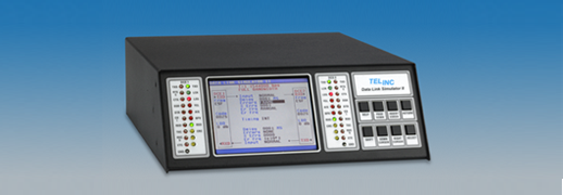
Data Link Simulator ll
The Telinc Data Link Simulator II simulates data communication facilities.
-
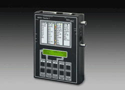
WAN Tester I
The Telinc WAN Tester I is a sophisticated, hand held bit error rate tester for
T-1, fractional T-1, E-1 and more. -
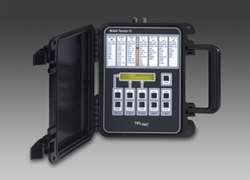
WAN Tester lI
The Telinc WAN Tester II is a sophisticated hand held bit error rate tester for
testing DDS, T-1, fractional T-1, E-1 and more. -
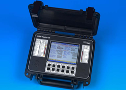
WAN Tester lll
The Telinc WAN Tester III is a sophisticated bit error rate tester for T-1, fractional T-1, E-1,
fractional E-1, T-3 and E-3 modems, multiplexers, CSU/DSUs, T-1 CSUs, DTUs, NTUs and TIUs. -
WAN Tester lllD
The Telinc WAN Tester IIID is a sophisticated bit error rate tester for DDS CSU/DSUs, DTUs, NTUs and TIUs.
-
Data Link Simulator ll
The Telinc Data Link Simulator II simulates data communication facilities.
-
WAN Tester I
The Telinc WAN Tester I is a sophisticated, hand held bit error rate tester for
T-1, fractional T-1, E-1 and more. -
WAN Tester lI
The Telinc WAN Tester II is a sophisticated hand held bit error rate tester for
testing DDS, T-1, fractional T-1, E-1 and more. -
WAN Tester lll
The Telinc WAN Tester III is a sophisticated bit error rate tester for T-1, fractional T-1, E-1,
fractional E-1, T-3 and E-3 modems, multiplexers, CSU/DSUs, T-1 CSUs, DTUs, NTUs and TIUs. -
WAN Tester lllD
The Telinc WAN Tester IIID is a sophisticated bit error rate tester for DDS CSU/DSUs, DTUs, NTUs and TIUs.