|
Simulates
communications facilities |
|
Built
into a standard lunchbox PC |
|
PC
can be used for other purposes |
|
70
data rates from 1,200 bps to 2.048 Mbps |
|
Inserts
delays up to 10 seconds in each direction |
|
Inserts
errors and timing slips in each direction |
|
User-defined
test sequences |
|
Five
pairs of interfaces: RS232, RS422/RS530, V.35, DS1 (T-1)
and G.703 (2.048 Mbps) |
|
Comprehensive
help screens |
|
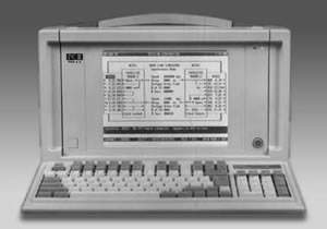
The
Telinc Data Link Simulator simulates a communications link,
inserting delays and introducing errors so users can determine
what effects these impairments will have on their systems.
The Simulator is built into a PC and includes on-line help
screens that make it easy to use, without training and without
reference to any manual. The PC is a standard 486 portable
which can be used for other purposes.
The
Telinc Simulator can be used in many applications including
testing protocols and error correction techniques, checking
new equipment prior to field installation and measuring performance
and reliability in various operating environments. It can
simulate a variety of communications facilities including:
 |
A
leased line with modems on each end |
|
A
DDS line with CSU/DSUs on each end |
|
A
T-1 line with T-1 CSUs on each end |
|
A
satellite facility with modems on each end |
|
A
2.048 Mbps facility with DTUs (Digital Terminating Units)
on each end |
|
The
Simulator includes five pairs of interfaces as standard equipment:
RS232, RS422/RS530, V.35, DS1 (T-1) and G.703 (2.048 Mbps).
It can introduce propagation delays in either or both directions
and can inject timing slip, bit, burst, frame and block errors
in either or both directions. Propagation delays can be up
to 9.999 seconds per direction for speeds up to 64 Kbps and
up to 1 second per direction for speeds from 72 Kbps to 2.048
Mbps. Delays, errors and speeds can be different in each direction.
The Simulator can also execute a user-defined sequence of
tests.
The
Data Link Simulator is easy to use. All operating parameters,
including interfaces, speeds, delays, errors and control signals
are illustrated on a single PC screen. Parameters are selected
by scrolling through values stored in the Simulator. Up to
49 configurations for each interface can be stored.
All
operations can be performed with only a few keys which are
defined at the bottom of every screen. A two-line description
appears on the screen explaining each parameter as it is selected.
At any point, the user can get help by hitting the H key.
Examples are illustrated for various configurations. In addition
to operating instructions, service and warranty information
is available on line.
|